 by Jonathan Jones/photos by the author
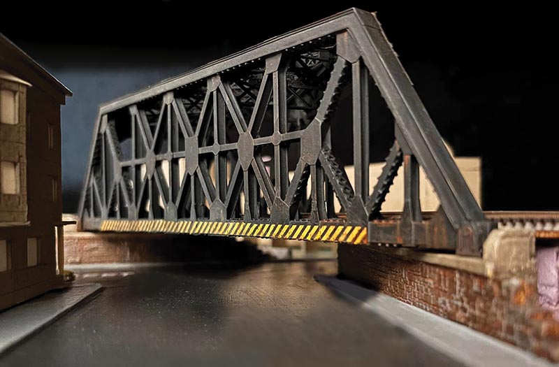
My model railroad represents the Central Railroad of New Jersey’s Newark Branch, a dense, heavy-duty urban line operated by the CNJ from the late 1890s into the early 1970s. A key scene in my recent layout expansion features three bridges crossing city streets, highlighted by a skewed Baltimore-style truss spanning Jefferson Street.
As a teenager just starting out in the hobby, I often read the work of the old hobby masters of the 1950s and 1960s. I was enthralled by their skills and methods, and dreamed that one day I might be able to build as they did. The complex angles and geometry of this bridge made it an ideal scratchbuilding subject, since no commercial model came close to capturing it. I approached this N scale project with the goal of using basic methods and materials — not out of nostalgia, but because they are inexpensive, simple, and familiar to me. Rather than present a step-by-step guide, this article is intended to demonstrate the broader materials, methods, and strategies behind the project — approaches that can be useful in modeling any complex prototype structure in any scale.
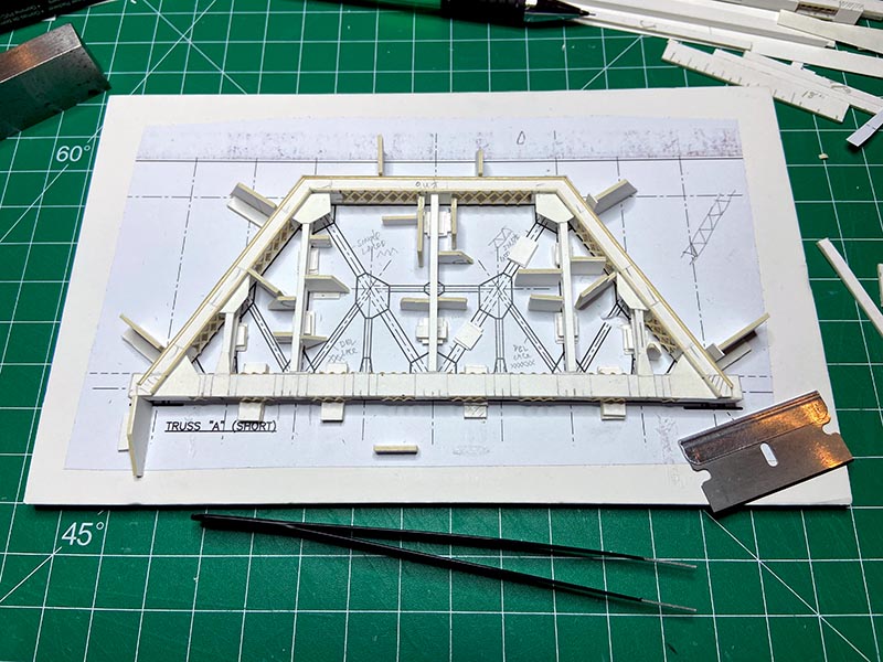
ABOVE: This view shows the partially completed short truss in its assembly fixture. The top chord and end posts were built as a single piece, while cardstock guides hold the remaining members in proper alignment during assembly. Stacked cardstock spacers center the vertical members and bottom chord beneath the wider top chord. Notes written directly on the fixture helped prevent assembly errors.
Prototype
The unusual shape of the Jefferson Street bridge resulted from three key factors: increased load requirements, reuse of the abutments from the original 19th-century bridge, and, most importantly, the irregular layout of the streets below. At this location, the bridge crosses a street intersection, but not directly over its center. As a result, one side of the bridge spans a single street, while the other crosses the intersection of two streets, making that side more than twice as long and creating the structure’s extreme asymmetry.
That asymmetry, combined with the bridge’s heavy construction and the rhythm of its many diagonals, verticals, and broad flat surfaces, is what makes it so visually interesting. From the north side, for example, it is possible to see both the front and side of the bridge from the same vantage point — an unusual and striking effect. As with any complex model, compromises were necessary, especially in N scale. But understanding the reasons behind the bridge’s distinctive design helped me focus on its essential features and decide how best to model them in a convincing way.
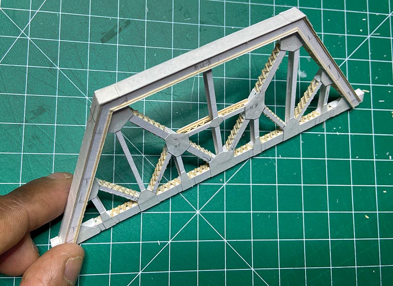
ABOVE: The completed short-side truss with all members and gusset plates installed. Additional plate detail has been added where the end posts meet the top chord. The intermediate horizontal member, built from wood and cardstock, appears slightly oversized.
A successful prototype model begins with sound research. One of my primary references was a 1907 Railway Gazette article detailing the bridge’s construction, complete with diagrams and photos. Trade journals of the period often highlighted major infrastructure projects, and many can now be found scanned online. That material was supplemented by structural diagrams and demolition photos of the bridge sent to me by members of my Facebook group, for which I am grateful. I translated these references into scale drawings using AutoCAD, and those drawings became the basis for all templates and assembly fixtures (see June 2026 RMC).
Tools and Materials
Traditional, old-school materials were used throughout this project: cardstock, stripwood, wood structural shapes, and white glue. Cardstock is easy to cut, takes paint well, and comes in thicknesses ranging from paper-thin sheets to heavy board, making it ideal for modeling flanges, plates, and gussets. I used high-quality brands such as Crescent, Strathmore, and Canson in 1/32” (.030”) and 1/16” thicknesses, along with .005”, .010”, and .015” sheets from pads.
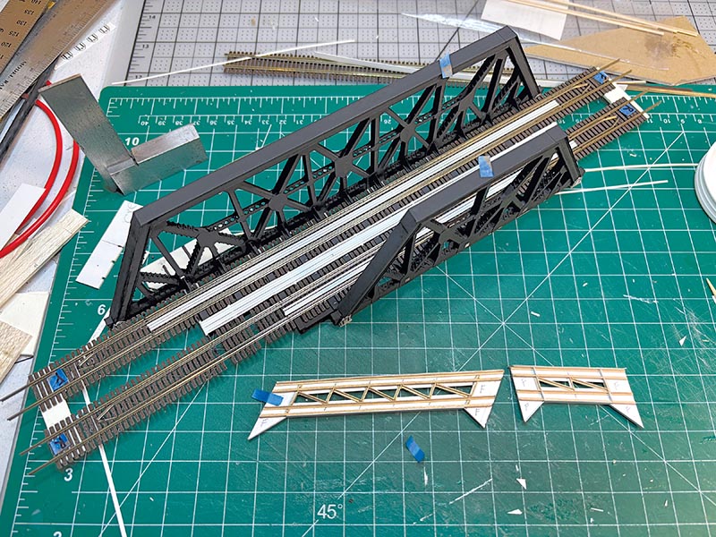
ABOVE: Styrene strips attached to simulate walkways. Bits of styrene support the walkways and join the two pieces of track into one manageable piece with the correct track center spacing. Guardrails were added following prototype practice.
Basswood strips were used for smaller structural elements such as angles and lattice bars, where near-scale size and consistency were important. The main sizes used were HO scale 1×2, along with 1/32” and 3/64” angle stock. Essential tools included calipers, a mechanical pencil, toothpicks for applying glue, a straightedge, and sharp knife blades. A pushpin also proved useful for marking intersections, corners, and endpoints, helping guide the blade and prevent overcutting…