 Otis McGee/photo by Dan Munson
Growing up in the 1950s, I occasionally “played with” trains. But, by my teens, my attention had turned elsewhere. Not until years later, in need of a distraction from the rigors that came with my career, did I return to model railroading. I was not particularly focused and, at the outset, I knew nothing about the growing interest in model railroad operations.
Attending the 1996 NMRA annual convention in Long Beach, Calif., I overheard discussions at the Special Interest Group (SIG) desk about operations that piqued my interest. I listened intently to some of these discussions and devoured the available written materials. I joined both the Operations SIG (OPSIG) and the Layout Design SIG (LDSIG) and soon began attending operating sessions. I became addicted to the concept of moving model trains with a purpose. Operations gave a new meaning to model railroading. I then decided that my next layout would be one that focused on operations.
Home Construction and Layout Design
In 2001, my wife and I built a new home. It would be a dream house for us and, importantly, it would have ample space for a layout. While the house construction was still in the planning stage, I reached out to legendary designer and dean of model railroad planning John Armstrong, to see if he would undertake a new project.
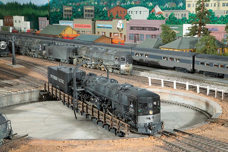
A cab-forward locomotive is turned for service in the Dunsmuir engine facility. Other AC class locomotives sit on the ready track, waiting to be called for helper service for heavy freights heading east out of Dunsmuir.
At John’s request, I sent him my “givens and druthers” for the layout. The givens included a 23×52’ room, with a 9’ ceiling and my desire to model Southern Pacific’s Shasta Division with its single-track main line between Redding, Calif., and Klamath Falls, Ore. My druthers were that the layout should have 40” minimum radius curves on its main line, as it would feature the 4-8-8-2 Cab Forward, AC Class, and 2-10-2 “Deck” locomotives. These and other long wheelbase motive power were used by Southern Pacific during the late steam/early diesel transition era on this division.
John accepted the challenge to design what became known as the SP Shasta Route, one of the last large layouts he designed. It was a masterful creation and he gave me his assurance that, if constructed as designed, it would fit the allotted space.
John’s plan called for “mushroom” construction with a single helix, one hidden staging yard, on the bottom of the helix, and three exposed yards – the feature yard at Dunsmuir, and two additional staging yards, one on top of the helix, and one in an adjacent room. The yard at Dunsmuir incorporates a one percent grade, as on the prototype. Use of the room’s walls would be maximized to support the main line trackage, the remainder being wrapped around both sides of the mushroom construction in the middle of the room.
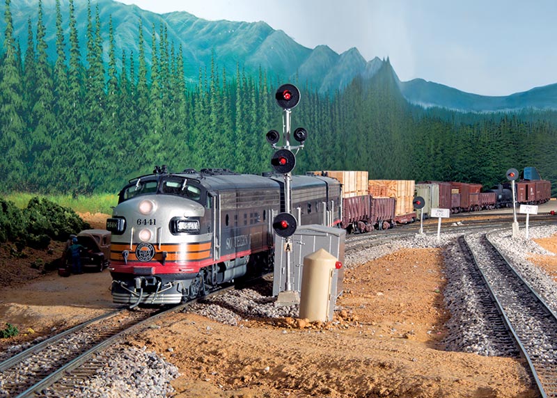
An all F-unit consist, with locomotive 6441 on the point, departs Black Butte, heading westbound to Dunsmuir. The twin lunar signals on the mast of the signal serve to control traffic into and out of the switches in the Black Butte yard.
John’s layout plans exceeded my expectations. They fully captured the essence of the area to be modeled, and several of its feature locations, including the Dunsmuir engine facilities and its yard, the Cantara Loop, Mt. Shasta City, and the nearby Hotlum trestle. Different views of majestic Mt. Shasta would be displayed on the backdrop.
The plans, however, were not accompanied by assembly instructions! Determining how to construct the layout would be left to me. While studying the plans, it became clear that certain preliminary work should take place in the layout room before the house was completed. This work included making certain that the stairway to the room above my garage would only minimally intrude on the layout floor space. Further, blocking would have to be installed in the 9’ ceilings before sheetrock was installed. This blocking would serve as attachment points for metal brackets to be hung from the ceiling to support the upper level of the mushroom.
Redding to Dunsmuir: Phase 1
We moved into our new home in September 2002. Layout construction began the following day. Tape was placed on the floor to outline the layout, and on the ceiling, to mark the locations for the center of the helix, the middle of the Dunsmuir turntable and the various blocking previously installed.
Construction of the helix was followed by benchwork to support the Dunsmuir engine facility and turntable. Using the marks on the ceiling, the exact centers of the helix and of the turntable were identified. Construction soon began on the Redding yard, which would soon be hidden by the four-level, double-track helix. More than 100 feet of Atlas Code 100 flex track and a dozen Peco turnouts, powered by Tortoise switch machines, would be installed in the helix that would serve as staging for eight full-length passenger and freight trains on sidings, while still allowing for an open main line to permit through passage of trains. At the top of the helix, another circular yard, this one for Klamath Falls, would be constructed…