 By Shawn Branstetter/photos by the author
As I begin to plan my small shelf layout, I want to incorporate as many diverse scenery elements as I can without overcrowding the scene. My plan has a road crossing at one end and roads have always been difficult for me to master. I decided to create a diorama first to fine-tune my skills before I attempted to build it on the layout.
Research is the key to every believable model. Even if, like me, you are building a freelance short line railroad. I began reading as much as I could about engineering roads and railroad crossings before I began my drawings.
Crossing Timbers
A crossing of this type would be typical for a private road, a low-traffic highway, or a farm crossing from the 1960s or earlier era. Some railroads still use timber crossings. Cast concrete and rubber-pad type crossings were introduced in the 1960s and are used in most cases to the present day. Each railroad and city has its own set of standards for grade crossings. I gathered my research and began my drawings.

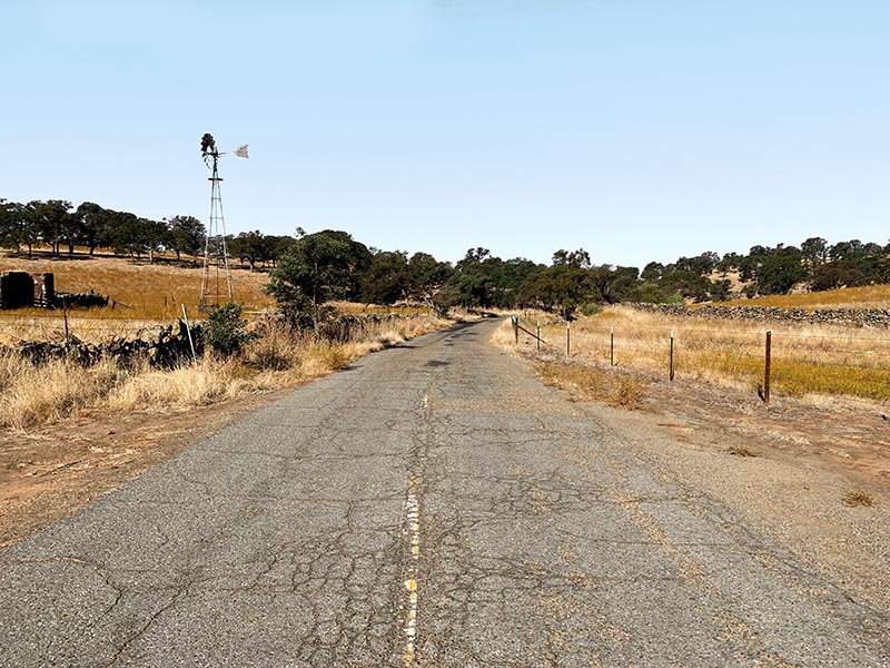
This typical asphalt road was the author’s inspiration.
Although the design looks simple, take a look at what goes into building a timber crossing. First is the roadbed. Typically, this is a crushed rock base which the ties rest on. Next are the crossing timbers. The height of the timbers and filler blocks will be determined by the weight or height of the rail. Typically timbers are approximately 8 by 10 inches; however, they will vary in height depending on the size of the rail. My rail is code 100 from Right O’ Way, which is close to 75-pound rail in Proto48. It’s typical for branch lines and short lines in the 1970s and earlier.
Wood filler blocks are spiked to the crossing timbers to secure them in place. Finally, the cross timbers are secured in place with a timber screw approximately 11/16 inch in diameter, countersunk one inch deep. While I built my crossing to Proto48 (1:48 finescale) standards, the techniques used apply to any scale or gauge. And although the size of your material may vary, the items needed will be similar to build your crossing.

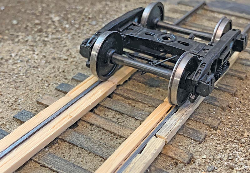
Proper clearance is being checked with both an NMRA style track gauge from Right-O’-Way and Proto48 trucks to ensure the wheels pass through the crossing freely. Any tight spots can be adjusted with a jeweler’s file.
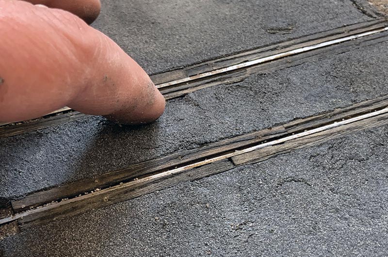
Using a razor saw and a dull X-Acto blade I distress the wood, creating quite a bit of wear on my timbers. I want mine to look well-used; however, your weathering should depend on the age and how well the crossing you are modeling is maintained. As you can see in the drawing, the timbers will need to be notched out for the tie plates and spikes. I sand the edges and then install the outside timbers.
While those are drying, I will turn my attention to the filler blocks. The size of the blocks will again depend on the height of your rail. The width should be fairly standard, between 2 7/8 inches and 3 inches. For Proto48/87 we are using scale flanges and these dimensions will work just fine. O and HO scale will need to modify or omit this detail for the flanges to clear properly.
I install my boards and then test the flange clearance before I install the inside timbers. There may be a few high spots, and I sand them smooth with a jeweler’s file. Once the equipment clears the blocks, I install the inside timbers. As per the prototype, you will need to taper the inside timbers slightly to clear the tie plates…


