 by Alvin Ho/photos by the author
After I finished work on my Quad Cities Rocket, I decided I was still missing something in terms of passenger service on my layout. Although the venerable Rock Island railroad was thinly stretched in the late 1970s all the way up to its bankruptcy, it still ran commuter trains between downtown Chicago La Salle and Joliet Union Station until it was taken over by the Regional Transportation Agency (RTA), known today as Metra.
At first, I contemplated building a few of the Budd bi-level cars that were commonly seen on the line; however, no kits were available for the cars, so I opted to create a more distinctive series of commuter cars on the Rock Island roster with available car sides. The 2700-series commuter cars, delivered between October and November 1949, were an order of 20 coaches equipped with four sets of sliding doors and 100 bench seats each. At the time, these cars were the first of their kind on the commuter line to be equipped with diesel-powered Waukesha Ice Engine air conditioning and a 10kW Enginator for in-car power. Even though these cars suffered severe steel corrosion from deferred maintenance on the Rock Island, they lasted until 1977–1978 when they were sold to a dismantler.
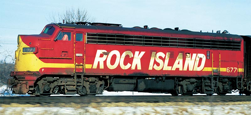
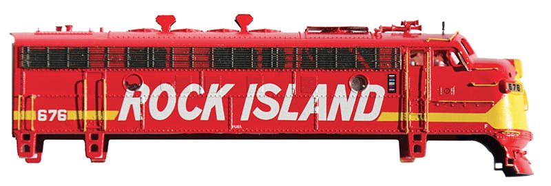
Sister engine No. 677 was built in March 1949 (construction number 6141) on EMD Order E975A. Mike Schafer photograph
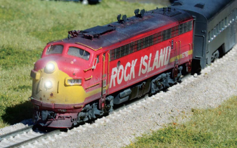
A pool of various cab units was always on the head of commuter trains coming out of La Salle Street Station, but passenger equipment varied between anything from the original heavyweight “Capone” coaches to the newest bi-levels. To pull this commuter, I decided on an F7 because it was commonly seen on the line (I already have an E8 in my roster). Even though E6s, E8s, and F7s were already re-equipped with HEP generators to work with the newer equipment, the Rock Island equipment was in such poor condition that the Joliet line was one of the first to receive new F40PHs and bi-level equipment from the newly formed RTA. As this new equipment came online in late 1977, the oldest passenger equipment was retired, and Rock Island passenger locomotives were displaced to freight service for the last three years of the Rock before its eventual demise in 1980.
The Locomotive
The Kato F7 started out as a Santa Fe unit that I stripped in 91 percent isopropyl alcohol. After a few hours of soaking and light scrubbing with a toothbrush, most of the paint came off cleanly. To start detailing, I added standard parts from BLMA’s E/F Unit Ultimate Detail Set for things like cab-side mounted walkways, ladder grab irons, cut levers, windshield wipers, and an MU receptacle on the nose. I bent nose grab irons and number board drop grab irons by hand with 0.008 phosphor-bronze wire, as well as additional curved eyebrow grabs with a lift ring on each to hold the corner bend in place since the one that came in the Ultimate Detail Set was the wrong size.
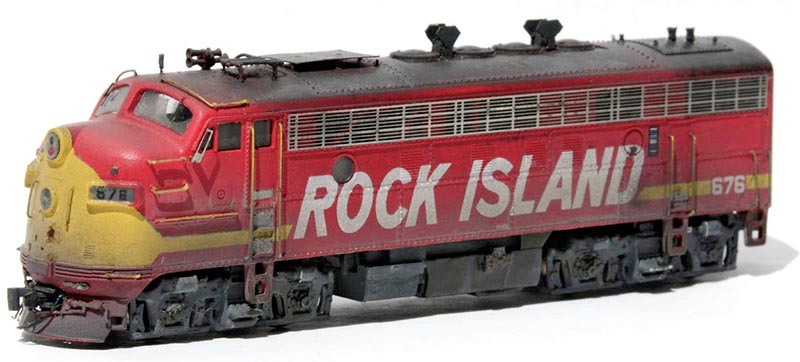
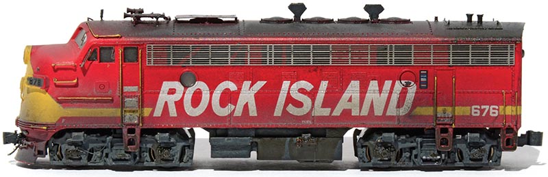
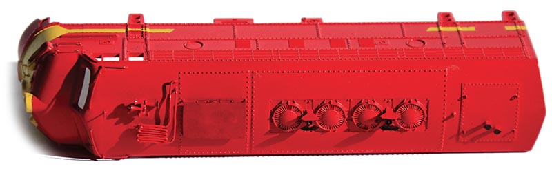 Alvin Ho added rooftop cooling coils and plate over the dynamic brake openings. He also modified the rear plate to represent the HEP installation.
After shaving off molded-on handrails with a micro chisel, I bent new hand rails for all the doors and rear access with more 0.008 phosphor-bronze wire and added them after basic painting to make sure there would be even paint coverage. I fashioned a speed recorder from a short length of 38-gauge magnet wire and a small drop of CA placed on the front roller bearing journal on the fireman’s side of the locomotive. Skirts were cut off the unit on both sides to leave a flat sill, while the hatches and fuel fillers were salvaged from the skirts and glued back onto the fuel tank in their respective places.
 Although there are few pictures of the roof, it was apparent there was some type of cooling coil on top of the cab that fed into two holes on the engineer’s side of the roof. To recreate this, I used 26-gauge magnet wire for all the piping with additional supports and standoffs made from 0.008 wire glued through holes in the roof. Right behind the piping leading to the cooling coil and on top of the dynamic brake hatch was a peculiar piece of flat metal that looked to be some type of antenna stand. The prototype has two fans under this flat piece, but I just cut a piece of 0.005 brass to size and glued it in place over the filed-down dynamic brake fan. The prototype 676 was equipped with a Nathan P5R24 early on in 1973, but it appears that by 1977, the horn had been changed to a different configuration more similar to a readily available BLMA K5HR24. I guesstimated the location of the horn due to no top-down views being available, mounting it adjacent to the rooftop cooling coil per instructions.
Instead of a standard steam generator commonly found on older passenger F-units, this unit was equipped with an HEP (Head End Power) generator in the rear hatch section to power the newly delivered bi-level cars. To model the presence of a HEP generator, I used pieces of 0.035 styrene rod for additional exhaust stacks coming out of the rear hatch and glued single MU hatches from the BLMA E/F Unit Ultimate Detail Set to the top of each to represent the flaps that cover the stacks. Later in its life, No. 676 was also equipped with flared spark arrestors between the fans. To model this feature, I cut pieces of stainless steel photo-etched fret from a BLMA fan set to create the side plates of the spark arrestors and glued them to the exhaust stacks between the fans.
Painting
Finally, in preparation for painting, I drilled out the classification lights with a No. 70 bit to allow marker lights used in commuter service. I also shaved off the old backup light and added a new casting from half of a Pyle sealed-beam headlight mounted on the left side of the rear door, almost parallel to the door window, and drilled the casting out to be lighted. Other details such as etched grilles and wind deflectors were added after painting to retain their stainless steel look. At this stage, I added an air hose to the front pilot with 0.012-inch stainless steel wire bent in a slight arc with the end crimped to represent a connector and trimmed MU hose attachments to glue onto the nose pilot as well.
After painting, I installed the LEDs that really made the F7 come to life; the number boards are separately controlled from the headlight and oscillating Gyralite, not to mention an additional new backup light and marker lights right on top of the number boards. All the white lights are sunny-white 1206s attached to the back of light tubes with Krystal Klear, while the marker lights are red 603s, all wired with 38-gauge magnet wire to the TCS decoder.

Finally, I added simulated sealed twin-beam headlight covers on the headlights with etched brass plates from Streamlined Backshop Services and put a drop of canopy glue on each to “glaze” a glass-like surface onto the lights.