
 by Robert Schleicher/photos by the author except as noted
The coaling trestle was one of the most common railroad structures found at most major yards with engine servicing facilities in the early part of the last century, and many survived into the beginning of the diesel era. The structure is, basically, a wood trestle to elevate the track 15 to 30 feet with a series of “pockets” built on one or both sides of the elevated track to store coal to be dumped into the waiting tenders of steam locomotives below.
Many modelers choose to build one of the tall wood, steel, or concrete vertical coaling towers, but the coaling trestle is a relatively simple project when broken down into sub-assemblies. I used styrene strips and scribed sheets, but the techniques are about the same if you opt for wood.
There were two versions of these coaling trestles, one lower with the unloading track about 15 ft. above the ground and the pockets positioned so they would be filled by shoveling the coal from gondolas like the Colorado Midland prototype at Basalt, Colo. The second and larger version of these coaling trestles elevated the unloading track to about 30 ft., with the track located directly above the coal pockets so the coal could be loaded into the open pockets by gravity. These larger facilities are not practical for most model railroads because it takes about 1,000 scale feet (about 11 feet when reduced to HO scale) to elevate track to 30-scale feet.
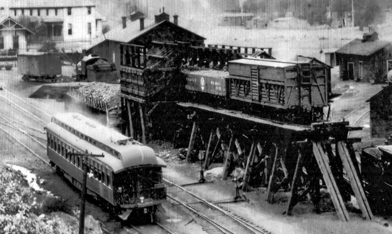
ABOVE: The coaling trestle is the most visible structure at Basalt, Colorado, in this 1888 view from the hillside north of town. —History Colorado collection
The Historic American Engineering Record has recreated plans for the Delaware, Lackawanna & Western coaling trestle at Scranton, Pa., from 1906. The facility had 16 coal pockets on each side as well as an elevated sand house on the end. The ash pit was beside the trestle. The DL&W coaling trestle was similar to a plan for a much smaller trestle shown in Buildings and Structures of American Railroads (by Walter G. Berg, C.E., published by J. Wiley & Sons in 1893), but with the pairs of coal pockets back-to-back to serve tracks on both sides. The elevated track was 30 ft. higher than the adjacent tracks. The coaling trestle at Basalt only elevated the track 15 feet and the total length from ground level to the far end of the level top was 250 feet (or 2.9 feet when reduced to HO scale), making it much easier to model.
Coaling trestles are seldom recreated by modelers but they were as common as the massive wood, steel, or concrete coaling towers that employed a bucket-belt conveyor elevator system lifting the coal from the dump bin below ground level to the top of the structure above the bins. There are many options to construct at least a dozen different wood, steel, or concrete coaling towers; however, I could only find one for a coaling trestle: Crystal River’s (mccarvillestudios.com) laser kit to build one of the Colorado & Southern coaling trestles at Vance Junction.
The prototype coaling trestles were similar on nearly all of the railroads, with a “standard” wood trestle used to elevate the track about 15 ft., then the coal bins or pockets were built around the trestle. Some trestles had pockets (bins) on both sides, others on just one side. Some of the tracks to fill the pockets were elevated on a dirt fill or embankment rather than a wood trestle, but those facilities were usually just one-sided sets of coal pockets like the C&S facility at Vance Junction. There were six other nearly identical versions at Sargents, Pine Grove, Como, Dickey and Pitkin, Colo., on the C&S narrow gauge. If you want to skip the complexity of the trestle you can build a slightly taller version of that Vance Junction facility for a standard gauge model.

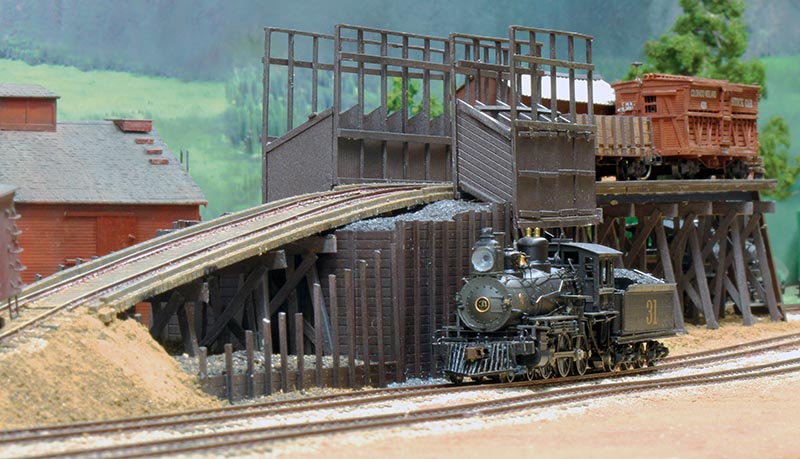
ABOVE: This HO replica of the Basalt coaling trestle, like the prototype, is designed to serve two tracks, with the center track elevated to allow the gondolas to be emptied into the coal storage pockets (bins).
Buildings and Structures of American Railroads included an illustration of a typical Burnett & Clifton design coal chute that was used by Union Pacific, Rock Island, Santa Fe, Burlington, Delaware & Hudson, and others. The book describes the functions of the various internal levers and latches that could control the flow rate of coal exiting the pocket. The visible faces of each pocket with the three horizontal braces are the bottoms of the aprons (chutes) which were lowered manually by cable or rope. Inside each chute was a second vertical wood door that was hinged at the top and counterweighted — it was that door that controlled the flow of coal. The levers and special hinges that controlled that door were usually purchased from one of the railroad hardware supply firms — this Burnett & Clifton mechanism was one of the most common. The diagram (on page 61) shows the vertical braces for the addition of roofs over both bins and the track, but most of these coaling pockets were built with the area above the tracks open with roofs only over the coal pockets (like those on the C&S).
The prototype for my model was open at the top. It is possible that they planned to add roofs but they were still open when the structure was demolished in 1917 to be replaced by a much taller version that allowed the hoppers and drop-bottom gondolas to dump coal directly into the pockets. Colorado Midland opted for 12 pockets, with four on the main line siding and eight on the stub-ended siding behind the trestle. The Basalt coaling trestle had a 200-ton capacity (about 17 tons per pocket). The locomotive tenders of the era had nominal capacity of 12 tons but another four or more tons were commonly piled on the deck of the tender, so each pocket had enough capacity to fill even an empty tender. A typical 34-ft. wood gondola of the period was rated at 30,000 lbs., so a single gondola load of coal was enough to fill two of the pockets. The railroad also placed the conveyor tower for the Basalt sand house to deliver sand to the locomotives on the far west end of trestle…