
Review by George Riley/photos by the author
For the vast majority of modelers, the enjoyable pastime of model making is a blend of design and construction skills with a mastery of tools. Each new tool gives us the ability, once its use is mastered, to take our modeling to a higher level of competence and perfection. Our first hobby knife and metal straight edge opened the door to what would become a life-long pursuit for most of us. The acquisition of a simple pin vise allowed our range of subjects to vastly expand in scope. The addition of an airbrush gave us the ability to apply professional finishes to our models. With the introduction of MicroLux LaserKnife 2525™ laser cutting machine, the average model railroader now has the ability to bring his modeling techniques into the 21st century.
This machine lets the home model maker attain the high precision inherent with laser cutting, which, in the last decade, revolutionized the model railroad kit market. Using this tool, the hobbyist can quickly make precise parts to upgrade his models, or even design and cut complete “scratch built” projects. The items that can be created using this machine are practically unlimited, except only by the imagination of the operator and his skill at computer-assisted drawing. Once a drawing file is generated, the hobbyist can cut just one part, a hundred parts, or several thousand, which makes this tool ideal for creating multiple models of the same design. With only a little practice, a part can be drawn in CorelDRAW® (or other user-friendly vector drawing programs) and cut out with the laser in less time and more accurately than if using a straight edge and hobby knife. In addition, the LaserKnife will precisely cut common modeling materials such as paper and cardstock, thin plywood and sheet wood, plastic styrene sheet and vinyl. The machine will not cut metal.
Each LaserKnife 2525 is delivered fully tested, and includes a comprehensive instruction manual, which makes for trouble-free and easy operation of the unit even for someone totally unfamiliar with the technologies involved. In addition, Micro-Mark readily provides technical support for any additional issues that may confront the user, but are not specifically covered in the manual.
Specifications and Set-Up
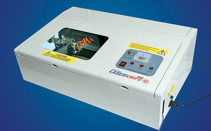
The LaserKnife 2525 is a full size laser cutting/engraving machine with a cabinet measuring 19″ deep by 32″ wide. The active cutting area measures a nominal 9.8″ square and, with careful design, will accommodate parts and projects ranging from N and Z scales up to, and including, large scale. If you set the machine to make multiple passes, the 40 watt laser unit will cut wood up to 3/16″ thick.
While this unit is designed for the home hobbyist, it should be placed on a caster-equipped work table, since it’s a bit bulky for putting away after every use. The LaserKnife is best suited to a dedicated work space, and has a couple of ancillary support items that need to be located near the main cabinet. The LaserKnife 2525 includes a transformer that allows the machine, which functions on 220vAC, to operate on standard 110 volt, 60 Hz house current. A ground fault interrupt (GFI) circuit outlet is recommended for this unit, since a water cooling system is used while in operation.
To operate the tool, a computer with a Windows 2000 or later operating system, connected to the Internet and running CorelDRAW version 11 or later, needs to be connected to the machine through the provided USB cable. The LaserKnife requires the full version of CorelDRAW and will not operate with student versions. Versions of CorelDRAW can be downloaded online, or program discs of no-longer supported versions (i.e., CorelDRAW 11 or CorelDRAW 12) can be affordably purchased. As long as the computer will support the program, an older computer can be put in service. Most Corel versions require only 2 GB of RAM and 1 GB of hard drive disc space for the program. CorelDRAW is very intuitive and features a number of resources and tutorials. So, learning the program is relatively easy. Plus, to get the user started, Micro-Mark includes a group of demonstrator files and a supply of workpiece materials, which will have the machine up and cutting in a very short time.
In addition to CorelDRAW, a plug-in for the program, called CorelLASER, will need to be downloaded from the Micro-Mark web site. CorelLASER adds functionality to CorelDRAW so that the computer will interface and operate the LaserKnife. A dongle (which looks like a memory stick and prevents unauthorized use of the program) is provided. It’s plugged into a USB port on the computer and permits communication between the computer and the LaserKnife.
Also included with the tool is an exhaust fan, which removes smoke that’s generated during the cutting process. To vent the smoke to the outside, a dryer vent needs to be installed in the work area. A section of vent tubing is also provided; however, the operator may need to add additional sections to reach an exterior wall and vent. These are available from any home improvement center or hardware store.
The LaserKnife utilizes a water cooling system to keep the laser “tube” from overheating. Keeping the unit cool is very important, since failing to do so will dramatically reduce the life of the laser tube. The owner needs to provide a five gallon bucket containing three gallons of distilled water. A submersible pump is included and installed in the filled bucket to circulate cooling water through the unit. Prior to every use of the machine, it’s a good idea to check that the water is circulating through the machine.
One additional ancillary item included for proper operation is a small air pump, which blows air through the cutting head to remove soot and dust from the lens and workpiece. Each of these items is plugged into the unit’s electrical sockets located on the rear panel of the machine. They automatically operate when the machine is powered up. All are designed to operate on 220 volts 60 Hz AC, so do not by-pass the LaserKnife’s electrical sockets and plug these into regular 110 volt wall current.
Making Your First Cut
Once the unit has been set up and all systems are operating, a demonstration file can be downloaded from the Micro-Mark web site onto the control computer. Micro-Mark recommends using one of the shanty files for a trial run initially to cut out sample parts from a piece of chip board (included with the machine) and, once satisfied, to cut out the provided scribed basswood.
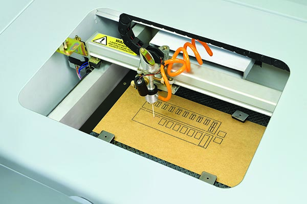
The LaserKnife 2525 is equipped with an LED “pointer” that projects a small red dot on the surface of the workpiece to show where the laser will cut. Before starting the first project, place a piece of stock on the cutting deck, then turn on the power. The red light of the pointer will then appear on the stock. Press the test button on the cabinet. The laser will fire and burn a single point on the stock. Now align the pointer to match the burned point and you’re set to go.
The LaserKnife not only cuts materials all the way through to create separate pieces, but can also etch patterns or pictures onto the surface of the work piece. The two operations can even be combined to cut out parts with etched surfaces, like stone work, bricks, shingles, siding or other patterns. These patterns can be drawn using CorelDRAW, or imported from a variety of graphic file formats (including CDR, AI, DXF, DWG, WMF, EMF, EPS, PSD, PLT, SVG, JPG, PNG, BMP, GIF, PDF, PCX, JPG and TIF).
The selection and cutting or engraving of a file is an easy 5- step process:
1. Begin by opening CorelLASER on the computer. This will open a screen that includes a laser cutter tool bar in the upper right hand corner.
2. With the CorelLASER screen on your monitor, open the desired file either from the demonstration files or one which is user-created. This file will appear in the center field of the screen.
3. Select the file or parts of the file that will be cut by simply clicking on them. Black squares and dashed lines will indicate the selected items.
4. With the items selected, choose either cut or engrave from the laser cutter tool bar. A small box will appear requesting approval to continue.
5. A large window will now appear with the selected items as an image in the center and a set of commands running down the right hand side. Click on the object and use the mouse or arrow keys to move it to the preferred start location; the laser cutting lens will move inside the cabinet so you can align the red pointer at the place on the material where the cutting process will begin. Set the power level on the LaserKnife’s cabinet to half way and press the cutting button to turn on power to the laser. Select the “Starting” command on the computer screen and the machine will begin cutting. Note: The lid of the cutting compartment has a safety interlock that shuts off the laser beam if the lid is opened.
Different materials will require different power settings and different travel speeds. The cutter program comes pre-set at a travel speed of 16 mm per second. Using this speed and setting the power control to 50% will easily cut the chip board provided with the machine as well as most 1/16″ thick basswood or balsa. Plastics should be run faster with a lower power setting to lessen the chance of melted plastic puddling along the cut line and welding it back together. Cutting through a piece of acrylic or styrene as well as thicker wood may require several passes with the laser. On the control screen, select the number of passes and check the “do not back” box. At the end of each pass, a box will appear on the computer screen asking if the action should be continued. Select “yes” and the next pass will start. Between passes, one can check to see if the part has been cut through before continuing further. Getting the right power setting and travel speed is more a matter of practice and experience than formula.
A good way to dial in the different settings is to use one of the demonstration files to cut different materials. For our test, the O scale shanty file was used to cut different thicknesses of paper, cardstock and wood to build the different versions of this model. To practice on plastics, the alignment guide was downloaded from the website and cut from 1/16″ thick acrylic stock provided with the LaserKnife, using multiple passes with the cutter set at around 1/3 power. This acrylic material cuts cleanly and is perfect for use with the LaserKnife. Additional acrylic sheets are available from Micro-Mark. The alignment tool will prove invaluable in making certain that materials are properly aligned and square with the cutter.
One beauty of this machine, in addition to the convenience of making multiple, high-precision parts, is that the design can be changed quite easily. For example, shanty parts can be flipped horizontally to make mirror images that have the door and roof peak on the opposite side of the building, and doors and windows can be added or deleted in just a few seconds.
Design Your Own Cutting Project
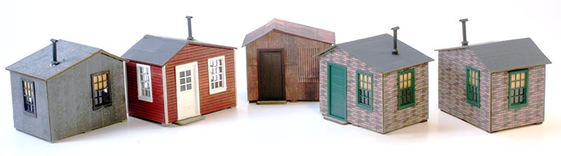
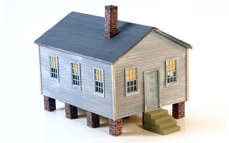
Once the demonstration files have been mastered, it’s time to cut a new project of your own design. A good place to start is with a simple structure. I chose a “shot gun” style house in O scale for my first project. Since this type of building can be found all over the country, it would be at home on nearly any layout or in almost any scene. In addition, with a few modifications, the basic structure can be used to create a small depot or freight house. With the addition of a steeple, it can also double as a small rural church. So, this is a building that can be used in multiple ways on a layout.
When designing a project, it’s a good idea to test cut the pieces from a sheet of inexpensive card stock, such as poster board or shirt cardboard. This will verify that the parts are properly sized and will fit. If the drawings indeed need to be modified, the more-expensive materials will not have been wasted.
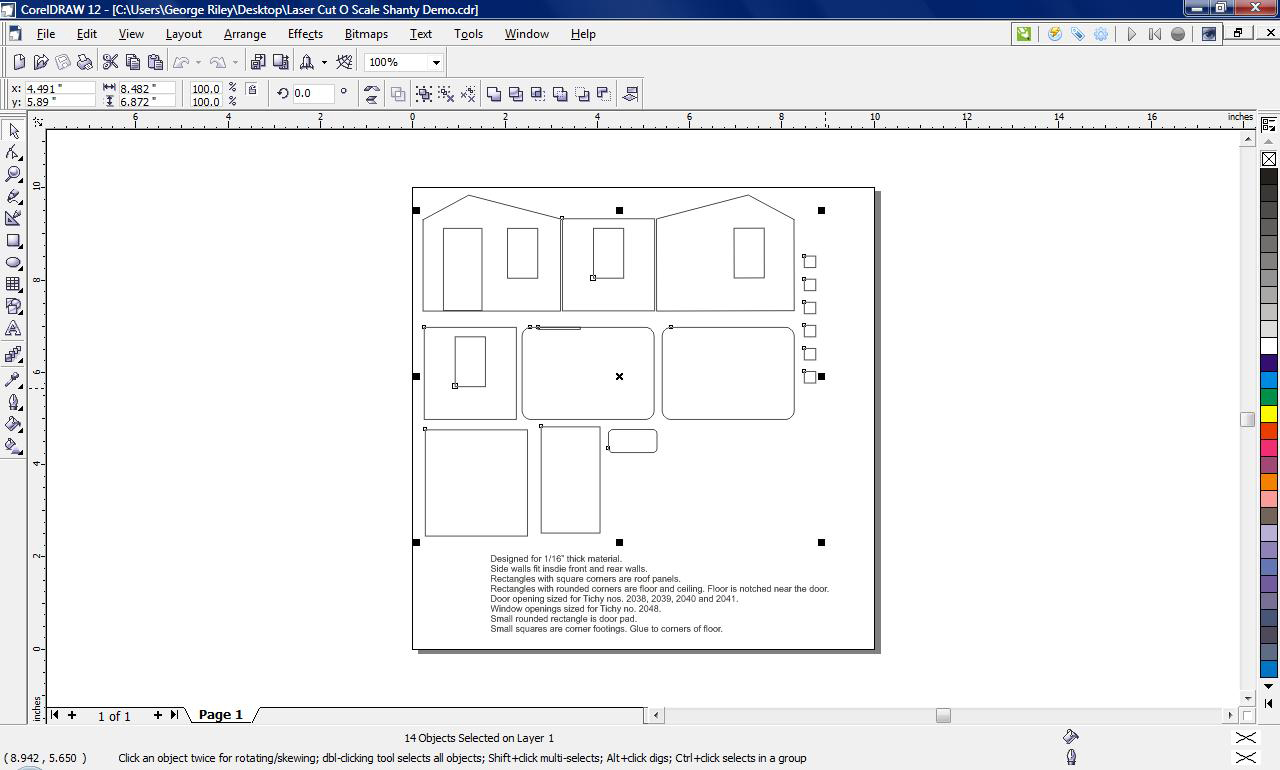
The first step is drawing the project. Getting started in CorelDRAW is very easy, particularly when designing a building. Begin by setting the page size to 9.8″ x 9.8″ to match the exact available cutting area of the LaserKnife. Select the rectangle tool and draw a rectangle on the screen. Dimension this to 2.25″ x 5″. This will be one side of the structure. Download the Tichy window and door templates from the Micro-Mark download site onto your desktop and select the type of window that is desired. Then copy and paste into position. This procedure can be repeated to place as many window or door openings as one desires.
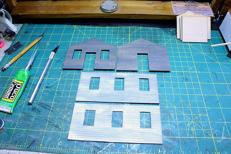
Next, draw the gable ends. Using the rectangle tool, draw a 2.5″ x 3″ rectangle. Add a 1″ peak centered on the top of this rectangle. Erase the top line from the original rectangle, then copy the end and paste it in another position to yield two identical ends. At this point, door and window openings can be added to the end drawings as desired.
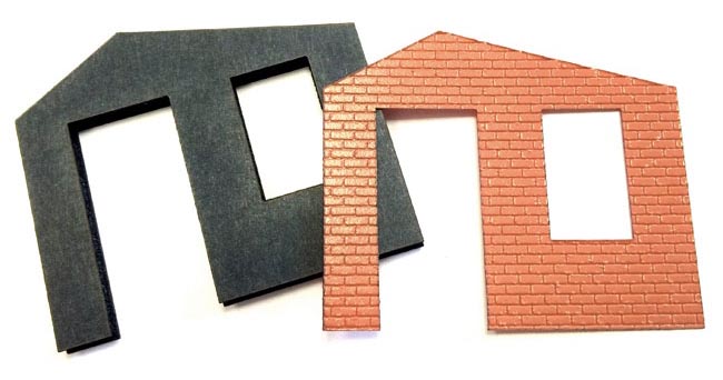
Now select the parts to be fashioned and cut them from a sheet of 1/16″ thick basswood sheet stock. For our version, clapboard siding with 3/16″ spacing was used for the sides and ends; however, any type of siding can be replicated from depression brick cut from a printed sheet laminated onto shirt cardboard, to embossed brick sheeting, as well as any variety of milled sheet wood siding.
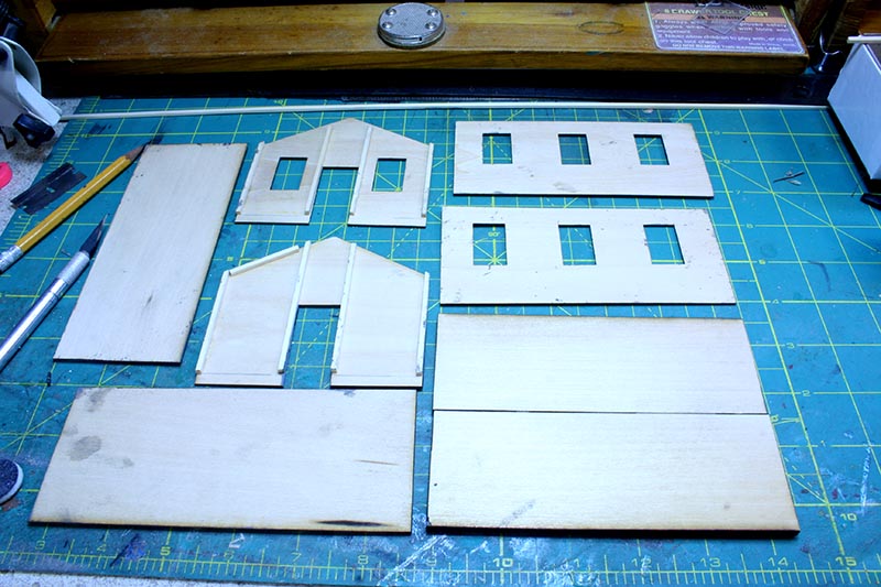
With the sides cut, draw out the floor. Since the stock used for the floor was only two inches wide, and the model will be a little over three inches wide, the floor was drawn and cut in two equal pieces, then glued together for the finished dimension. Or, glue to pieces of raw stock together to form a piece that’s wide-enough for the final floor, and use the LaserKnife to cut to the precise final size. In addition, the slope of the roof was measured and two roof pieces drawn that measured a quarter inch wider on both ends and one side to allow for roof overhang.
Assembling Your Project
When the basic pieces had been cut, they were stained with gray transparent oil-based stain, which, once dry, was over-stained with white pickling stain. Several strips of 3/32″ square strip wood were also prefinished for use as exterior corner posts. To speed the assembly process, pre-finish parts prior to cutting. Items like the floor and other concealed parts, which were not pre-stained, were sealed with sanding sealer to prevent warp and swelling. This includes the 3/16″ square corner and interior bracing, which was sealed as well.
Tichy plastic window and door castings were primed with gray primer, and then streaked with white artist oil paint. The white paint was wiped with a clean cloth to produce a weathered paint effect. This lets the windows blend with the stained wood siding, giving the effect of heavily-weathered paint and graying wood.
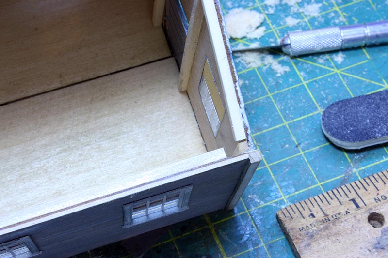
With this simple project, assembly is very straight forward. Glue 3/16″ square basswood stock flush with the corner edges of both of the side pieces. When cutting the corner blocks, make sure that they are short enough to allow the floor to fit flush into the wall assembly. When the glue has set on these sides, attach the end walls to each of the sides. Do not overlap the ends of the end walls with the side walls, but leave a recess in the corner into which 3/32″ square basswood exterior corner trim is applied. This technique for finishing corners makes for a very strong joint, which will hold up to even the roughest of handling and transport.
Now that the four walls have been assembled, interior bracing made from 3/16″ square stock is glued in place. As a general rule, the bracing should be attached along the edges where other parts will be glued to the assembly. At this point, the floor can be slid into place to help square up the structure. The floor should be a snug fit and left unglued, so that it may be removed later should additional interior details or interior lighting be added. At this point, the doors and windows can be installed with their glazing added. The Tichy window castings include not only clear properly sized clear glazing, but also have paper shades.
Bevel the gable edges of the roof pieces with a small block plane or sanding block so that they meet at a tight angle when applied to the building. When satisfied with the two roof pieces, they can be attached to the wall assembly and held in place with rubber bands while the glue sets up.
A quick way to replicate a tarpaper rolled roof is to pre-paint a sheet of peel and stick label paper with dark gray Rustoleum Automotive primer. While the paint dries, draw a series of rectangles that measure a scale 3’ wide by the actual length of the structure. In O scale, this will measure 0.75″ x 5.5″ for the shotgun house. Cut the strips with the LaserKnife, peel off the backing and apply to the roof.
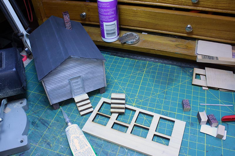
The next set of details that need to be added are the foundation pillars, chimney and steps. In warmer climates, these buildings are usually set well off the ground on masonry or concrete footings to minimize the ravages of termites. Further north, the foundations are closer to the ground to lessen heat loss, or the structure is set on an enclosed foundation that forms a basement. This project is set on twelve piers cut from 3/8″ square basswood set at 3/4 ” high (or 3 scale feet in O scale) . Wrappers are cut from Clever Models Old Brick files (downloadable at www.clevermodels.com) and printed on 60 lb cardstock using an inkjet printer. They are drawn and then cut with the LaserKnife. These wrappers are then glued around each pier using Aleene’s Tacky Glue and then attached to the underside of the floor. The same technique is also used to make a chimney, which is then glued in place on the roof.
Simple steps were created using 3/16″ thick basswood sheet stock cut into stepped rectangles, then glued up in layers. To cut this thicker stock, the LaserKnife was set on half power and made the cuts required in six passes. The stair assemblies were primed and painted prior to being attached to the building.
A World of Possibilities for Any Model Railroader
As with all of our projects, additional small home-made and commercial detail parts can be added to this basic building to enhance the model. Using laser cutting, craftsman level precision is easily attained by anyone who is able to employ the easy operation of the LaserKnife and the basics of CorelDRAW. With only a few hours of practice, an amazing array of precise parts and models can be created in an almost limitless range of materials. Based on these attributes, Micro-Mark’s LaserKnife will allow the hobbyist to reach new levels with their models and may well prove to be “the ultimate tool” in anyone’s workshop.
This review appeared in the January 2016 issue of Railroad Model Craftsman
Micro-Mark
340 Snyder Avenue
Berkeley Heights, NJ 07922
800-225-1066
MicroLux LaserKnife 2525™
Item #:86097
$1,995.00 plus shipping
Includes: Lighted steel cabinet with durable paintwork, honeycomb platen, clear-vision window, internal power supply, control panel and control electronics; Air compressor and tubing for blowing away cutting/engraving particles; Water pump and tubing to circulate cooling water through the laser tube; Exhaust fan and duct to remove smoke from the cabinet; 110vAC to 220v AC power supply and transformer; Power cord and USB cable; CorelLASER software plug-in; CorelLASER User’s Key; Sample model structure drawings; Lens focus gauge; Start-up test materials (wood, acrylic and chipboard sheets); Spare fuse; Lid safety switch; Instruction manual, maintenance instructions, wiring diagram, and tips and tricks.
Customer Provides: Computer running Windows 2000 or later operating system connected to the Internet; CorelDRAW version 11 or later; 5-gallon plastic bucket to contain 3 gallons of distilled water; Vent to outside; GFI protected circuit.