
 by Matt Boucher/photos by the author
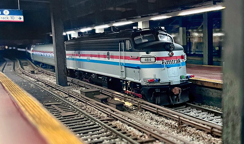
Third-rail electrification is often used where overhead wire catenary is not practical, often applied to commuter districts and rapid transit lines. While there were numerous trolley and interurban lines around the country, the first large-scale railroad applications were in New York City on the Interboro Rapid Transit subway lines in 1904 and the Long Island Rail Road in 1905. Electrical pickup was made by special “shoes” attached to the outside of the truck frames that slid along the top of the third rail, with a wooden cover suspended over the rail to shield it from weather and accidental human contact. When the Pennsylvania Railroad opened Penn Station in 1910, both LIRR and PRR used third-rail power to reach the new station through tunnels under the East River and Hudson River, respectively. Later, PRR converted to overhead AC catenary, but third rail remained for the LIRR trains, a system that continues to this day.
One day while having coffee, staring at the track plan for my HO scale rendition of Amtrak’s Northeast Corridor, the proverbial light bulb lit up. Wouldn’t it be interesting to take what was planned as a six-track stub end staging yard and transform it into New York’s Penn Station?
When I think about that historic station, a few things come to mind that would be essential to creating a plausible model. Penn Station is a dark, cavernous space populated by high-level concrete platforms, surrounded by numerous support columns. Probably the most important detail is representing the electrification, namely the third rail. After some thought, it quickly became evident that modeling New York Penn Station would not be an easy feat.
Without the availability of a commercial kit that could recreate a convincing look of North American third-rail, specifically like that found in New York City, I would have to build my own. I spent a bit of time researching on-line and studying pictures. Third-rail infrastructure consists of four components — an insulator seat or chair, rail, protective board cover, and supporting brackets. I found that there was no real method to the madness. In general, the third rail was supported every fifth tie. However, I discovered that sometimes there were exceptions, depending on location or the system, such as subway or heavy rail. Now that the basics were understood, it was time to find appropriate material to create a convincing model.
Method
Luckily, Peco, as part of their European third-rail product line, offers an insulator chair (IL-120), which made for a great starting point. The insulators are designed to clip to the head of the rail, in this case, MicroEngineering Code 70 rail. By drilling a #64 hole, these can be fastened into a footing or tie. Using Evergreen .080 x .125” (no. 116) styrene strip, cut it at 1.5 scale feet to create a footing that extends the tie. As previously mentioned, it’s more common to find an insulated support at every fifth tie, but use what works for you.
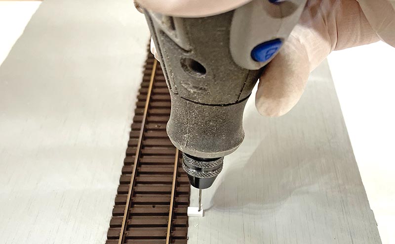
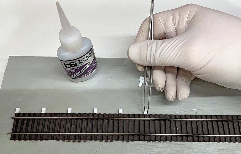
Mark out every fifth tie and drill the required size hole approximately 0.5 scale feet center from the edge. Position all the insulators on the rail and dry-fit them into each hole on each footing. Once satisfied with the dry fit, using cyanoacrylate adhesive (CA), permanently glue the rail and insulators down.
Next are the protective board cover and support brackets. For the support brackets, use Tichy Train Group .020” phosphor bronze wire (no. 1103) and Evergreen .015” x .080” styrene strip (no. 114) for the board cover. There are two different methods for the supporting brackets; first the “intermediate brackets” and second the “footing brackets.” The “intermediate brackets” are bent at 90 degrees. The horizontal bend is about 1/4 of an inch long toward the track and soldered to the outside of the third rail, centered between every insulated footing. Leave about 3/4 of an inch vertical above the third rail…