
 By William E. Botkin/photos by the author
The Delaware, Lackawanna & Western (DL&W) stretched from the shores of the Hudson River opposite New York City at Hoboken, N.J., across northern New Jersey into New York’s Southern Tier to terminate at the Great Lakes port of Buffalo, N.Y. In the early 20th century, the Lackawanna developed its own distinctive designs for its depots, towers, bridges, and signals. The unique aspects of the infrastructure are an important part of my modeling, as I depict the area around the busy junction at Port Morris, N.J., in 1952 and 1953. As such, I wanted to model the various types of signals used by the Lackawanna in that timeframe.
Since my layout includes both main line and branch line operations, there were a variety of signals required including color light on masts, color light on signal bridges, color light on cantilever signal bridges, dwarf signals and semaphore signals. While some were available commercially, such as the semaphore signals, others required building individual signals from commercially available parts.
The objective was not only to model the signals correctly, but to make them working signals that would show the various prototypical aspects depending on track occupancy, position of turnouts or crossovers ahead of the signal and the aspect of the next signal. Victor Hand had the knowledge and skills to develop the techniques that I used to build individual signal circuits that used the three critical inputs noted above. He used traditional circuit design employing relays and diodes and provided hands-on guidance in building the signal circuits for my railroad.
Semaphores and Train Order Signals
The simplest signals to recreate were semaphores. Lackawanna phased out the use of semaphores on the main line by the early 1950s, but continued to use them on branch lines into the early years of the Erie Lackawanna. Tomar’s Union Switch & Signal (US&S) lower-quadrant semaphore models are very close to the type used on the Lackawanna on their “old main” and branch lines. For these, it was a matter of repainting and decaling the blades to match DL&W practice and repainting the masts weathered black from silver. Circuitron Tortoise motors and their actuating mechanisms were used to drive the semaphores’ operation.
Mast Signals
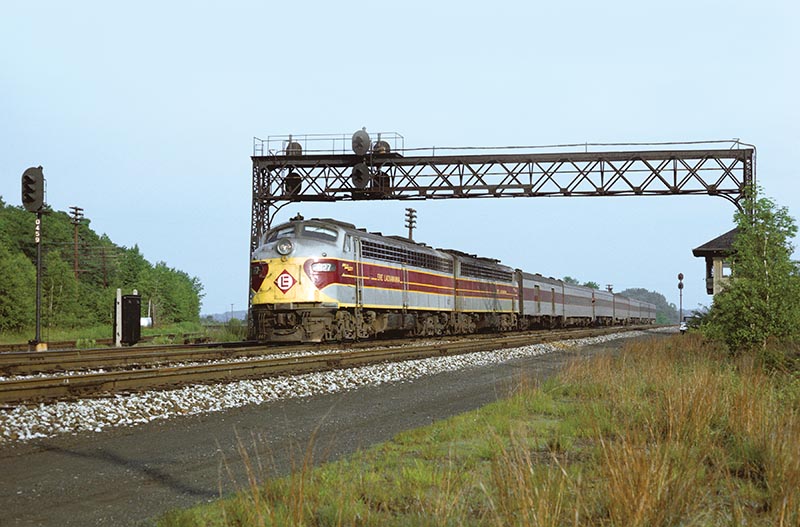
Lackawanna generally used double-head two-over-two color light configurations with red in the top position on the upper head and green in the bottom position on the lower head (Opening photo). The other two positions were yellow. In the early 1950s, there were only eight possible aspects with red over yellow lights in the top head and yellow over green in the bottom head. Even with only seven (top red with or without a number plate is the same output for modeling purposes) possible aspect outputs, there were some signals I was modeling that resulted in 15 different input combinations depending on occupancy, position of the turnout or crossover and the next signal’s aspect or output.
In addition to the double-head signals, DL&W also used single-head three-light signals in some locations. These would only have indications displayed for three aspects with red in the top position, green on the bottom and yellow in the middle.
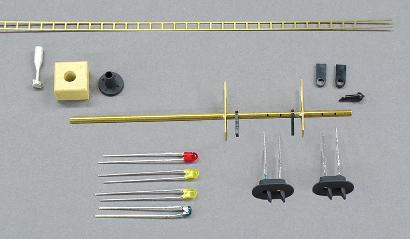
Building the mast signals requires some soldering skill, but in general, no other special tools or skills. If you are building several signals, it is best to set up an assembly line to speed up construction. After assembling the parts, the first step is to determine the height of the mast including the base, then cut the 3/32 inch brass tubing to the correct length using a cut-off wheel on a rotary tool. In the case of the DL&W, mast heights were not uniform, so if you are modeling a particular location, it is best to refer to prototype photos. Clean up the outside and inside of the tubing using a small round file.
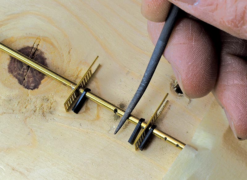
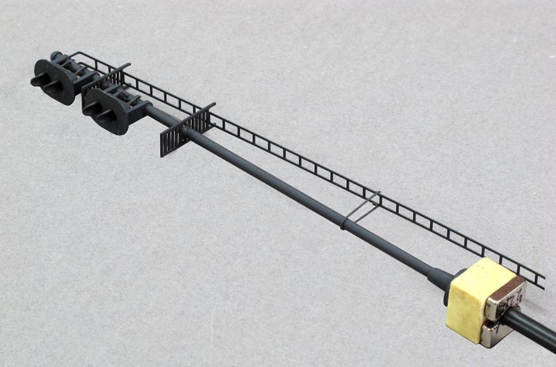
Based on the prototype, determine the correct location on the mast for the heads and maintenance platforms. While Oregon Rail Supply (ORS) does make plastic maintenance platforms, I prefer brass platforms and ladders that can be soldered to the mast for durability. Integrated Signal Systems (ISS) offers brass parts for signals. Creating a jig to correctly position the platforms helps in the process (Photo 3), Before soldering the platforms to the mast, you should trim the length of the platform to suit the angle of the ladder. For my signals, I trimmed the upper platform more than the lower platform to accommodate the angle of the ladder. Before soldering both platforms in place, slide the two ORS signal head brackets in place between the platforms. Since the Oregon Rail Supply brackets are plastic, wrap the mast in some wet tissue to prevent the heat from melting the brackets. Cut the ladder stock to the required length and solder to the platforms…