
 by Jonathan Jones/photos by the author
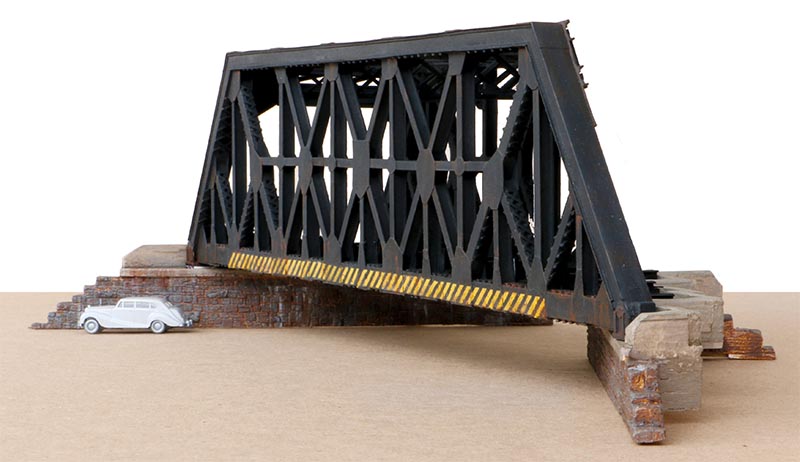
My N scale layout depicts the long-gone Newark Branch of the Central Railroad of New Jersey in the 1950s. This was a busy, heavily built branch line that ran through the heart of downtown Newark’s urban fabric. Much of the line is elevated on an embankment, crossing above the dense grid of city streets on earthen fill. And where there are streets, there are bridges, lots of bridges, and all of them need proper support in the form of abutments.
Abutments provide support for bridges at each end and often serve a dual purpose as retaining walls. Because my railroad does not always cross over streets at a 90-degree angle, I would need a technique to make abutments in several different configurations — ranging from straight, to L-shaped — and simulating different materials including concrete and stone.
I decided to use balsa wood and basswood as the base material for my N-scale models. Sometimes overlooked because of their coarseness, these were simple, cheap, readily available materials that were easy to fabricate to match my prototype. I could have used 3D-printing — which I have used elsewhere — or even cast them out of plaster, but wood allows for faster and more direct modelmaking. And I enjoy working with wood.
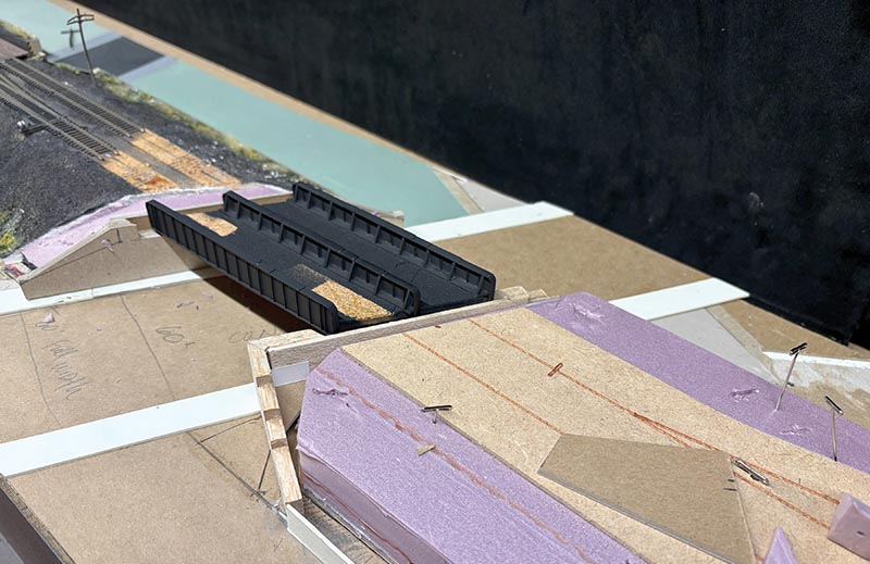
ABOVE: This bridge will have simulated concrete abutments. A cardboard mock-up is shown at the far end of this plate girder bridge. This abutment is straight with sloped walls. Note the angled cutout that forms a “shelf” that the bridge footings sit on firmly. The opposite abutment has a 90-degree angle forming an L-shape with a stepped wing wall forming the base of the “L.”
Concrete Abutments
My first step in making a concrete bridge abutment was to test the fit of the bridge (a plate girder in this case) and make a mockup of each abutment using cheap cardboard laminated together to achieve the correct thickness.
I also used the mockup to establish the overall height of the abutment, its size and shape (angled, stepped, etc.), and especially the height of the shelf that the bridge footings would sit on. This last part is critical to the look and feel of the entire installation so it will be level with no humps in the track where it meets the bridge. To provide the feel that the bridge is firmly supported and capable of carrying a heavy load, it is also important that the bridge footings sit on the shelf with no gaps.
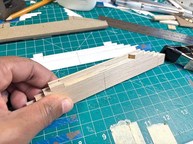
Once this step was complete, I made a pattern out of cardstock that I used to transfer to the balsa wood. For concrete abutments, I used 3/32” and 3/16” thick balsa wood sheet and 1/32 x 1/16” basswood strip. These would be laminated together to represent concrete between 3 and 4 feet thick in N scale, which approximates what I have seen from my prototype research.
ABOVE: The front and back pieces have been glued together to form a “pocket” that the bridge will fit into. The sides of the pocket are angled to follow the geometry of the railroad. A centerline allows me to place the piece accurately when testing the fit on the layout. Note the wood grain runs horizontally to match how formwork would have been placed before casting the concrete. The back piece has been cut slightly oversize and will be trimmed to match the front piece.
When I was happy with the pattern (sometimes I made changes after the mock-up), I transferred it to the balsa wood by tracing the outline onto a piece of 3/16” sheet, being careful to be aware of the grain direction. Next, according to the outline, I cut the top profile of the abutment and a wide “notch” for where the bridge would sit.
When this was complete, I laminated an oversized piece of the 3/32” sheet to the back side, making sure the bottoms of both pieces were aligned. I used UHU glue for this and clamped the pieces together tightly using cardboard and wood scraps so the clamps would not leave dents in the soft wood. The UHU adhesive is not water-based, which helps to minimize warpage. After the glue had dried, I trimmed the back piece so all edges were flush.
The next step was to apply any remaining details and treat the balsa wood, with its coarse grain, so it would reasonably simulate concrete. I added a small overhang to the shelf with the basswood strip. Once that was done, I coated the entire piece with artist’s sandable hard gesso — a liquid primer available from well-stocked artist supply stores. This material fills in the grain, evens everything out, and provides a good base for painting. I applied three coats, lightly sanding between each coat…