
 By Steve Brudlos/photos by Dan Munson
My wife, Sherry, and I were high school teachers in Albuquerque, N.M. In June 1970, we drove back to our home town of La Crosse, Wis., to visit our parents. My father-in-law was a switchman and yardmaster at The Milwaukee Road’s La Crosse yard. He didn’t like seeing his son-in-law idling about, so he asked me how I would like to work for the railroad as a “summer job.” In July 1970, I started my “summer job” as a brakeman working out of St. Paul, Minn. The summer job somehow became permanent. The time passed and, after spending ten years as a conductor and brakeman, the company finally dragged me into management. Another 25 years flew by while I worked as an operations manager in various capacities and locations for The Milwaukee Road, Soo Line, and finally Canadian Pacific Railway.
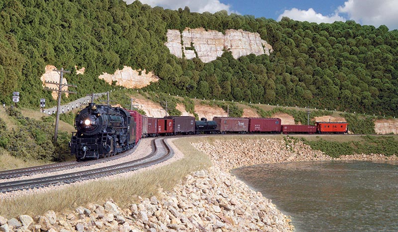
Newly retired, my wife and I moved from the Twin Cities to La Crosse so that she could care for her aging father in 2007. Our new home in La Crosse had a nice, large basement. I needed a hobby to keep me occupied in retirement and model railroading seemed to fill the bill. Besides, I figured I knew something about railroading. I laid claim to a 15×40-foot area of the basement and, after drywall, flooring, and lighting upgrades, I was ready to start construction. My “home” subdivision on the Milwaukee Road was the River Sub, which followed along the west bank of the Mississippi River in Minnesota between the Twin Cities and La Crosse. I planned to model this area. It is a beautiful locale, and I knew it well. I realized that I could not model the entire River subdivision, so, initially, I chose to model the area between Wabasha and Lake City, including the historic river town of Reads Landing.
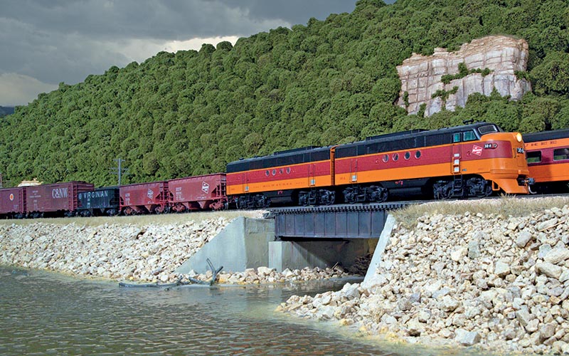
A westbound Milwaukee Road freight passes eastbound Train No. 6, the Morning Hiawatha, on the double-track main line along the western shore of the Mississippi River.
In 2008, I started constructing the layout. My plan was to build a free-standing, single-deck lay-out along two walls of the basement with a wide central peninsula creating a “U-shaped” layout. I planned a helix on both ends of the layout, which would lead down to a staging yard located under what was to become Lake City. I planned to model the late summer of 1950. And, like the real railroad, the lay-out would have double-track Rule 251 territory with semaphores governing train movements. Modeling the year 1950 during the “transition era” would allow running steam locomotives, as well as first-generation diesels.
Layout Construction and Trackwork
I wasn’t breaking new ground in layout construction. I planned to use open grid, L-girder construction using 1×4 girders and 1×4 joists. I used half-inch plywood for the subroadbed supported on risers attached to joists spaced 16 inches apart. For towns and yard areas, I used plywood sheets, again supported on risers. This framework was supported on 2×2-inch legs attached to the girders with carriage bolts. I installed “T nuts” and 3/8-inch carriage bolts into the bottom of the legs to allow for height adjustments.
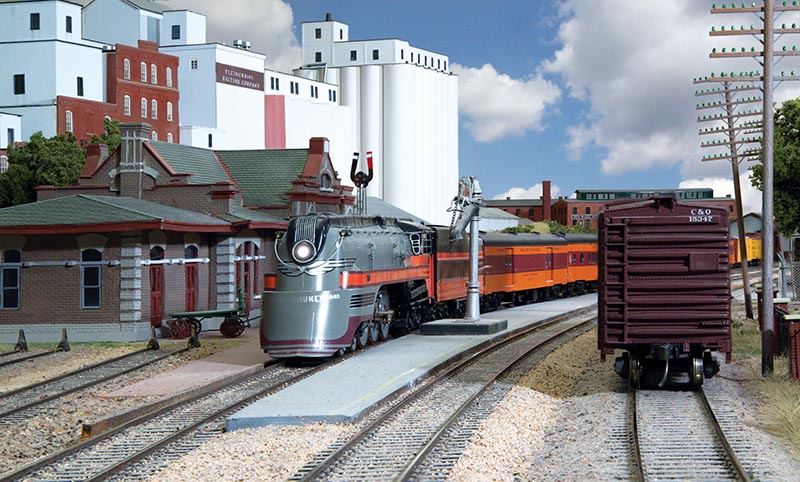
Class F7 Hudson No. 100 pulls Train No. 6, the eastbound Morning Hiawatha, to a station stop at Red Wing.
With the basic framework of the layout completed, I started laying down the track. I chose Peco Code 83 flex track for the main tracks and Micro Engineer-ing Code 70 flex track for sidings and industrial trackage. I selected Micro Engineering No. 6 turnouts in Code 83 and Code 70 for appropriate applications. The track roadbed consisted of Woodland Scenics “TrackBed” secured to the subroadbed with DAP Dynaflex 230 clear caulk. The track and turnouts were secured to the roadbed with the same caulk. I powered all turnouts with Tortoise slow motion switch machines controlled by double-pole/double-throw switches mounted in the fascia.
I didn’t bother to draw up track plans. I just started building. Since I was modeling an actual railroad with which I was thoroughly familiar, the only constraint I could envision was the inability to model actual track lengths. I worked with selective compression to replicate the actual track configurations of the various yards…